1 Introduction
The CAN bus was developed by the German BOSCH company, and the maximum rate can reach 1Mbps. CAN's fault tolerance is particularly strong, and the CAN controller has built-in powerful error detection and processing mechanisms. In addition, unlike traditional networks (such as USB or Ethernet), CAN nodes will not transmit large data blocks between nodes. A CAN message can transmit up to 8 bytes of user data. Short data packets can also make the system better The stability. The CAN bus has a bus arbitration mechanism and can form a multi-master system.
2. CAN Standard
CAN is a serial communication bus defined by the International Standards Organization. It was originally used in the automotive industry to use two signal buses to replace the complex wiring in the car. CAN bus has high anti-interference, self-diagnosis and data error detection functions. These features make CAN bus widely used in various industrial situations, including building automation, medical treatment and manufacturing.
The CAN communication protocol ISO-11898: 2003 standard introduces how information is transferred between devices on the network, and which layered items conform to the Open System Interconnection Reference Model (OSI). The actual communication is carried out in the physical medium of the connected device, and the characteristics of the physical medium are defined by the physical layer in the model. The ISO11898 architecture defines seven layers. The lowest two layers in the OSI model are used as the data link layer and the physical layer, as shown in Figure 2-1.
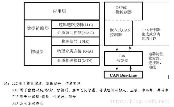
Figure 2-1: ISO 11898 standard architecture layering
In Figure 2-1, the application layer establishes a communication link for the upper application specific protocol, such as CANopenTM protocol. This agreement is maintained by CiA, user and manufacturer organizations all over the world. For details, please visit the CiA website: can-cia.de. Many agreements are dedicated, such as industrial automation, diesel engines or aviation. Another industry standard example is the CAN-based protocol, DeviceNetTM developed by KVASER and Rockwell Automation.
3. Standard CAN and extended CAN
The CAN communication protocol is a multiple access protocol based on carrier sense, collision detection and arbitration based on message priority (CSMA/CD+AMP). CSMA means that each node on the bus must monitor the bus before attempting to send a message, and can only send it when the bus is idle. CD+AMP means to resolve collisions by arbitrating the programmed message priority bit by bit, and the message priority is located in the identification field of each message. Messages identified by higher priority levels can always gain access to the bus, that is, the last logic high in the identifier will continue to be transmitted because it has a higher priority.
The ISO-11898:2003 standard, with an 11-bit identifier, provides the highest signal rate from 125Kbps to 1Mbps. Later revised standards used an extended 29-bit identifier. The standard 11-bit identifier bit field is shown in Figure 3-1, which provides 2048 different message identifiers, and the extended 29-bit identifier bit field is shown in Figure 3-2, which provides 537 million different message identifiers.
3.1 Standard CAN
Standard CAN has only 11-bit identifier, and the data length of each frame is 51+(0~64)=(51~117) bits. Note: Bit stuffing is not counted (Bit stuffing will be described in Section 5 of this article).

Figure 3-1: Standard CAN---11 bit identifier
· SOF-start of frame, dominant (logic 0) indicates the start of a message, and is used to synchronize nodes on the bus.
· Identifier-Standard CAN has an 11-bit identifier to determine the priority of a message. The smaller the value of this field, the higher the priority.
· RTR-remote transmission request bit, when you need to request information from another node, this bit is dominant (logic 0). All nodes can receive this request, but the frame identifier determines the designated node. The response data frame is also received by all nodes and can be used by interested nodes.
· IDE-When the extension bit of the identifier is dominant, it means this is a standard CAN format, and when it is invisible, it means this is an extended CAN format.
· R0-reserved bit (may be used in future standard revisions)
· DLC-4-bit data length code indicates the number of bytes of data to be transmitted, a frame of CAN can transmit up to 8 bytes of user data
· Data 0~8-Up to 8 bytes of user data can be transmitted
· CRC-16-bit (including 1-bit delimiter) CRC check code is used to check the transmission data segment before the user data area (including the data area).
· ACK-2 bits, including response bit and response delimiter. In the message frame of the sending node, the ACK two bits are recessive bits. When the receiver correctly receives a valid message, the receiver will send a dominant bit to the sending node during the response bit period to indicate the response. If the receiver finds an error in this frame of data, it will not send an ACK response to the sending node, and the sending node will retransmit this frame of data later.
· EOF-7-bit frame end flag, all recessive bits. If these 7 bits appear dominant, it will cause a stuffing error.
· IFS-7-bit frame interval flag, it takes a certain time for the CAN controller to correctly put the received frame into the message buffer, and the frame interval can provide this time.
3.2 Expand CAN
Extended CAN has a 29-bit identifier, and the data length of each frame is 71+(0~64)=(71~135) bits. Note: Bit stuffing is not counted (Bit stuffing will be described in Section 5 of this article).

Figure 3-2: Extended CAN---29 bit identifier
The contents of the extended CAN message relative to the standard CAN message are as follows:
· SRR-instead of the remote request bit, it is recessive. Therefore, when standard frame and extended frame transmission conflict with each other and the basic identifier of the extended frame is the same as that of the standard frame, the priority of the standard frame is higher than that of the extended frame.
· IDE – It is a recessive bit that indicates the extended frame of the flag bit. The 18-bit extended identifier is followed by the IDE bit.
· R1-reserved
4. CAN message
4.1 Arbitration
The basic principle of a typical CAN is shown in Figure 4-1. It can be seen from the figure that the bus logic state is opposite to the driver input and receiver output logic. Under normal circumstances, the logic high level is 1 and the logic low level is 0, but the CAN bus has a logic high level of 0, which is called dominant, and the logic low level is 1, which is called recessive. Therefore, the driver input of many transceivers will have built-in pull-up resistors. When there is no input, the CAN bus will behave as recessive (logic low).
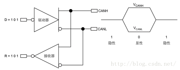
Figure 4-1: Inverted CAN bus logic
When the bus is idle, the node that first starts to send a message gets the right to send.
If multiple nodes access the bus at the same time, CAN uses non-destructive, bit-by-bit arbitration to determine which node uses the bus: each sending node starts arbitration from the first bit of the arbitration domain (identifier and RTR domain), and continuously outputs dominant The node with the most level (0) can continue to send. Therefore, a CAN message with a lower identifier value has a higher priority. A CAN message with an identifier value of 0 has the highest priority because it outputs the most dominant level.
4.2 Message type
CAN has four different message types: data frame, remote frame, error frame and overload frame.
5. Bit stuffing mechanism
The frame start, arbitration field, control field, data field and CRC checksum field are all encoded by bit filling method. Bit stuffing means that whenever the transmitter detects that there are 5 consecutive bits with the same logic in the bit stream, it will automatically insert a complement bit in the bit stream. For example, if there are 5 consecutive dominant bits, then 1 recessive bit is automatically inserted after the 5 dominant bits. The receiver will automatically delete this inserted stuffing bit.
The remaining bit fields (CRC delimiter, response field and frame end field) of the data frame or remote frame are fixed in form and are not filled. Error frames and overload frames are also not filled.
CAN network synchronization requires enough rising edges, which is one of the purposes of bit filling specified in the CAN protocol. Other functions of bit stuffing: to ensure that the data frame will not be treated as an error frame (consisting of 6 consecutive dominant or recessive bits), and to ensure the correct recognition of the end of frame flag (7 consecutive recessive bits).
6. Error detection and fault definition
CAN bus has high robustness, which may be attributed to CAN's multiple error checking mechanisms. The CAN protocol has formulated five error detection methods: three are located at the message layer, and two are located at the bit stream layer. If an error occurs in a data frame, the frame will be discarded, and the receiving node will send an error frame. This will force the sending node to repeatedly send the wrong message until the receiving node receives it correctly. If the same message has repeated errors, after reaching a certain number of times, the sending node can turn off the sending function to reduce the impact on the bus.
Error detection at the message layer includes CRC and ACK. The 16-bit CRC field contains 15-bit checksum and 1-bit delimiter. The ACK field includes 1 acknowledge bit and 1 delimiter.
The CRC check error is well understood. It produces CRC check on the data field and the bits before the data field. Because the data stream of a CAN message is very small (up to 8 user data), the 15-bit CRC has excellent error detection capabilities.
How does the ACK domain work? This is stipulated by the CAN protocol, that is, after the sending node sends a frame of data, the receiving node must reply to the sending node. If the sending node does not receive the response signal from the receiving node, it will think that it has failed to send and retransmit the data.
The third method of error checking at the message layer is format checking. This check will monitor those fields in the message that must be recessive bits. If a dominant bit appears in these fields, a format error is detected. These fields include SOF, EOF, ACK delimiter and CRC delimiter.
One of the error detection of the bit stream layer is that every data bit sent to the bus will be monitored. If the sent bit is not the same as the bit on the bus, a bit error will occur. This monitoring mechanism does not monitor the bit of the arbitration domain, because when multiple nodes compete for the bus at the same time, the node with a higher priority may overwrite the bit of the arbitration domain on the bus.
Another error detection mechanism in the bit stream layer is the bit stuffing rule: after 5 consecutive identical logic bits, if the logic of the 6th bit is still the same as the first five, a bit stuffing error will occur.
7. Network topology
CAN uses differential signals and requires a pair of signal wires. It is recommended to use twisted pair wires. The network topology is shown in Figure 7-1. The use of differential signals can suppress common mode interference, increase system reliability, and allow higher speeds to be used.
The high-speed ISO 11898 standard stipulates that the maximum transmission rate of CAN is 1Mbps. At this rate, the maximum transmission distance is 40 meters (30 nodes are connected, and CAN signals are not isolated). It is recommended that the maximum branch length of the node is 0.3 meters, and it is recommended to use shielded or unshielded twisted pair cables with a characteristic impedance of 120 ohms.
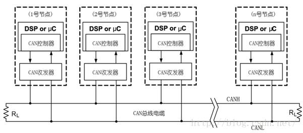
Figure 7-1: CAN bus network topology structure diagram
8. Terminal matching
The terminal matching resistance is equal to the characteristic impedance of the transmission cable. The characteristic impedance of the transmission cable is provided by the cable supplier, which is generally approximated as Z=√(L/C). Among them, L is the inductance per unit length of the cable, and C is the capacitance per unit length of the cable.
Due to the CAN transceiver structure, it changes from recessive to dominant and driven by transistors, so it is very steep, but from dominant to recessive, it needs a terminal resistor to discharge, otherwise it will discharge slowly due to the distributed capacitance of the wire , Resulting in bit width error. Therefore, the so-called short-distance, low-baud rate CAN bus without terminal resistance is wrong.
RS485 is different from CAN bus. Because RS485 transceivers generally have built-in failure protection circuits, no terminal matching resistance is allowed at short distances and low baud rates.
9. Cables and Wiring
The CAN bus adopts differential signal transmission. If a shielded twisted pair is used, the shielding layer should be grounded at a single point.
Figure 9-11 lists the CAN cable with a single shielded layer analysis and connection line demonstration.

Figure 9-1: Cable signal distribution, grounding and terminal matching
Generally, the smaller the cable cross-sectional area, the larger the distributed capacitance, distributed inductance, and DC resistance. When the communication distance is long, capacitance, inductance and DC resistance will cause signal attenuation, waveform distortion and jitter.
Generally, the cable supplier will provide a signal attenuation chart.
The curve shown in Figure 9-2 shows the relationship between the attenuation and frequency of the 24-AWG cable.
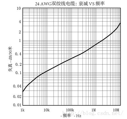
Figure 9-2: Signal attenuation
10. Differential signal voltage amplitude
As shown in Figure 10-1, the two signal lines CAN_H and CAN_L are both about 2.5V in a static state. At this time, the state represents logic 1, which is called recessive; CAN_H higher than CAN_L represents logic 0, which is called dominant. Normally, the CAN_H voltage is 3.5V and the CAN_L voltage is 1.5V.
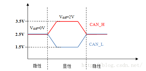
Figure 10-1: CAN level amplitude
The CAN standard stipulates that only when the differential voltage on the CAN bus is greater than 0.9V can be recognized as a dominant level, and less than 0.5V can be recognized as a recessive level. The level between 0.5 and 0.9 cannot determine the level polarity. As shown in Table 10-1.
Table 10-1: Relationship between differential voltage amplitude and level polarity

Table 10-2: The relationship between the number of terminal matching resistors and the amplitude of the differential voltage
When wiring the actual project, it is easy to miss or add more terminal matching resistors. We can measure the CAN differential voltage amplitude to evaluate whether the terminal matching resistance is missing or added. If the wire resistance is not included, the terminal resistance is fixed at 120 ohms, and the differential voltage of the single-node CAN bus is shown in Table 10-2.

11. Cable cross-sectional area and communication distance
The cable cross-sectional area has a great influence on the communication distance, especially long-distance communication. Distributed capacitance, distributed inductance, and DC parameters on long-distance transmission lines can cause signal attenuation. Many CAN communication applications have the characteristics of long distance and low baud rate. For example, the company's KTC161 communication control system uses 10kpbs, and the transmission distance should be no less than 3km. In this case, the DC resistance of the transmission cable has a great influence on the transmission distance, because this DC resistance will divide the voltage with the terminal matching resistance.
As shown in Figure 11-1, the 1st node and the 2nd node are separated by 5km, the DC resistance of the transmission cable used is 12.8 ohm/km, and the terminal matching resistance is 124 ohm. The amplitude of the differential voltage of the waveform sent by node 1 is 2V. When it passes through a 5km transmission cable to node 2, the amplitude of the differential voltage is about 1V, and the signal is attenuated by half! As we mentioned in Section 10 above: the differential voltage on the CAN bus> 0.9V can be recognized as a dominant level. Now the 2nd node only has a 1V differential voltage, and its reliability has become lower.
In order to ensure reliable data communication, a useful rule of thumb is: the differential voltage amplitude of the end node is not less than 1.2V.
Note that the influence of distributed capacitance and distributed inductance is deliberately ignored in the figure, so the transmitted waveform has no distortion
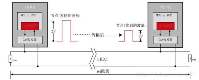
Figure 11-1: Schematic diagram of DC resistance divider of transmission cable
For twisted pair cables, assuming that the terminal matching resistance is the same as the characteristic impedance of the cable, the cross-sectional area and maximum communication distance can be referred to Table 11-1:
Table 11-1: Relationship between cross-sectional area and maximum communication distance

In order to minimize the voltage attenuation caused by the DC resistance of the cable, a larger terminal resistance value (150~300 ohms) helps to increase the length of the bus. For example, a twisted pair cable with a cross-sectional area of 1.5 mm2 is used, and the characteristic impedance of the cable is 120 ohms. When transmitting data with a baud rate of 5kpbs, using a matching resistance of 120 ohms can transmit up to 5km, but using a matching resistance of 300 ohms can transmit 7km!
12. Baud rate, terminal matching resistance and communication distance
The above section 11 describes the relationship between the cross-sectional area of the transmission line and the communication distance. In this section, we will keep the cross-sectional area of the transmission line constant and check the influence of other parameters on the communication distance. Taking the shielded twisted pair with a cross-sectional area of 1.5 mm2 as an example, the relationship between its baud rate, terminal matching resistance and communication distance is shown in Figure 12-1. Among them, when the baud rate is high, the communication distance is limited. For example, 1Mbps, the CAN communication distance after signal isolation is about 25~30 meters (most of the actual projects will electrically isolate the CAN communication module, and the isolation device will reduce the communication distance). The baud rate is low and the terminal matching resistance is increased, allowing long-distance communication. For example, when 5kbps and terminal matching resistance is 390 ohms, the communication distance can reach 10km!
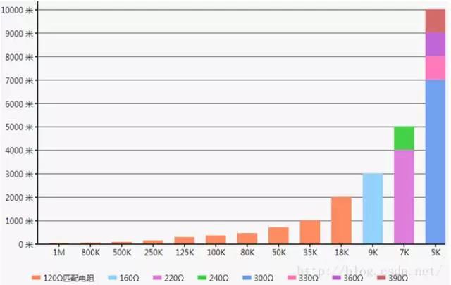
Figure 12-1: Relationship diagram between baud rate, terminal matching resistance and communication distance
13. Signal delay and communication distance
In the case of high baud rate, the signal delay that restricts the CAN communication distance. When the signal passes through the isolation optocoupler, transmission cable, and ESD device, it will cause signal delay. If CAN's resynchronization is not enough to make up for this delay, it will cause sampling errors and eventually CRC errors.
Figure 12-1 shows the maximum communication distance of a transmission cable with a cross-sectional area of 1.5mm2 under different baud rates and terminal matching resistances. When the baud rate is 1Mbps, the communication distance is about 30 meters. The transmission loss of a 30-meter communication cable is negligible. At this time, the main influence on the communication distance is the signal delay.
Generally, the transmission cable delay is 5ns/m, the high-speed optocoupler delay can reach 25ns, and the magnetic coupling isolation device delays 3~5ns. In the CAN communication system, an excellent delay standard is:

among them:
tl_MAX: Maximum delay time
tBIT: bit time
Taking 1Mbps as an example, its bit time is 1us, then tl_MAX<0.245 × tBIT = 0.245 × 1us = 245ns. The signal can reach this delay time when the signal is transmitted on a 1.5mm2 transmission cable for 49 meters. In addition, the signal rising/falling edge time and the delay of the isolation device, ESD device, and PCB trace are added. In the actual project, the 1Mbps baud rate is 1.5 Only 30 meters can be transmitted on the mm2 transmission cable.
This is why the RS485 baud rate can reach 10Mbps or even 50Mbps, while the maximum rate of the CAN standard is only 1Mbps.
Table 13-1 gives the reference standards for determining the delay. In actual projects, the recommended signal delay is in the good column.

14. Minimum distance between nodes
CAN bus is a distributed parameter circuit whose electrical characteristics and response are mainly determined by the inductance and capacitance distributed along the physical medium. The physical medium here includes connecting cables, connectors, terminals, and CAN devices connected along the bus.
Under no-load conditions, the characteristic impedance of the transmission cable is approximately Z=√(L/C), where L is the inductance per unit length of the cable, and C is the capacitance per unit length of the cable. As the load increases, the capacitance on the transmission line increases (load capacitance, load and bus connection line capacitance), and the characteristic impedance of the transmission cable becomes smaller than that under no-load conditions. If the load is relatively concentrated, the characteristic impedance of the transmission cable in the load area and the characteristic impedance of the cable in the idle area are quite different, which will cause impedance mismatch. As shown in Figure 14-1.

Figure 14-1: Schematic diagram of CAN bus principle with unbalanced load
The CAN bus impedance mismatch will cause signal reflections. What makes the CAN arbitration mechanism worse is that during the arbitration period, two or more nodes may send multiple dominant bits at the same time. As shown in Figure 14-1, when the switch S1 switches from the dominant state to the recessive state at t=0, the differential output voltage of the CAN driver is Vs, and the differential signal on the bus will change from the dominant state (Vs) to stable The recessive state (0V). This signal waveform will propagate down the bus, and when it reaches the load area of the bus, the reflected voltage caused by the impedance mismatch will return to the source.
The minimum safety distance d between the load and the load is a function of the total load capacitance CL of the device and the distributed capacitance C per unit length of the cable, which is defined as follows:

The device lumped load capacitance CL includes the total capacitance of CAN transceiver pins, connectors, isolation devices, protection devices, printed circuit board traces and other physical connections.
3.3V CAN transceivers can generally achieve 16pF capacitance, please refer to the transceiver data manual for details; printed board traces are generally 0.5pF~0.8pF/cm, which depends on the material and structure of the circuit board; connectors and protection devices ( For example, the capacitance value of an ESD device may have a large range. Please refer to the device data manual for details; the distributed capacitance of the unshielded twisted pair medium is about 40pF/m~70pF/m.
Figure 14-2 shows a clearer graphical display.
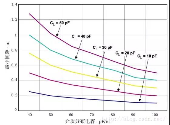
Figure 14-2: Minimum CAN device spacing
15. Signal bit sampling point location
The signal bit sampling point refers to the position where the CAN node recognizes a level logic. The CAN standard subdivides each bit on the bus into different stages, as shown in Figure 15-1. As can be seen in the figure, each bit is divided into four consecutive parts: synchronization section, propagation section, phase buffer section 1 and phase buffer section 2. The sampling point is located after the phase buffer section 1, and the duration of the synchronization section, the propagation section, the phase buffer section 1 and the phase buffer section 2 are all programmable, so the sampling point position is also indirectly programmable.

Figure 15-1: Segmentation diagram of each data bit
Generally, the CAN node is sampled once for each bit (also can be sampled 3 times, mostly used in low-speed occasions), and the sampling point position is in the area after 50% of a bit. This is to stabilize the signal level. The later the sampling point, the more stable the waveform. But it is not as far back as possible. When the sampling point position exceeds 95%, errors may be caused due to bit deviation during transmission. CIA recommends that the sampling point is 87.5% of a bit time. In actual projects, it is generally set to 70% to 90%. Most automobile manufacturers specify the sampling point to be 70 to 80%.
The sampling point is slightly behind, such as 80~90%, which is conducive to long-distance transmission. Increasing the synchronization jump width SJW value in the node baud rate register (increased to 3 unit time) can increase the bit width and the tolerance of the sampling point.
16. Baud rate deviation
Due to the influence of the crystal oscillator, the actual value of the CAN communication baud rate will deviate from the theoretical value. If the baud rate deviation between two nodes is large, it is easy to cause problems such as increased bit error rate or communication failure.
The CAN standard stipulates that the deviation between the set theoretical baud rate and the actual baud rate shall not exceed ±1%; the baud rate deviation that the node needs to tolerate shall not be less than ±3%.
17. Node capacitance
In the process of CAN communication circuit design, node capacitive reactance is easily overlooked. Node capacitance includes transceiver pin capacitance, PCB trace capacitance, ESD device capacitance, and other wiring capacitance.
The CAN standard has a strict definition of the capacitive reactance of the node. The capacitive reactance affects the slope of the rising edge and the falling edge. As the node capacitive reactance increases, the rising and falling edges will slow down, resulting in bit time distortion and increased bit error rate. The slower rising and falling edges will increase the signal delay, and affect the signal transmission quality and communication distance at high baud rates.
Node capacitive reactance is not easy to measure and requires special instruments. When designing the circuit, it is necessary to estimate the total capacitance of the devices used in the CAN interface circuit in combination with the typical values given in the data sheet. For high baud rate, single node capacitance is recommended to be<100pF, and multi-node capacitance recommended value is shown in Table 17-1. Low baud rate applications can relax the requirements.

Table 17-1: Maximum single node capacitance
18. Number of nodes
The number of nodes that can be connected to the network is determined by the minimum load impedance that the transceiver can drive. The maximum number of nodes is given by the following formula (considering the worst case):

among them:
Rdiff_min: the minimum differential input impedance of the transceiver
RL_min: The minimum load resistance that the transceiver can drive
RT_min: minimum terminal matching resistance
In the above formula, the minimum differential input impedance of the transceiver (Rdiff_min) and the minimum load impedance that the transceiver can drive (RL_min) are determined by the transceiver chip, and the minimum terminal matching resistance (RT_min) is determined by the characteristic impedance of the transmission cable and the specific Application decision.
Take the PCA82C251 transceiver used by our company as an example, the minimum differential input impedance of the transceiver Rdiff_min = 20K ohms, the minimum load impedance that the transceiver can drive RL_min = 45 ohms, assuming the minimum terminal matching resistance RT_min = 120 ohms, The maximum number of nodes is 112.
19. Common mode voltage range
Common-mode voltage refers to the potential difference between the sending node ground and the receiving node ground on the bus. Excessive common mode voltage will affect the system, which may cause intermittent restarts, deadlocks, increased bit error rates and even damage to the equipment. In the long-distance communication system, the problem of common mode interference will be more prominent, because as the distance of the communication line increases, the ground loop will pick up more noise and increase the common mode voltage.
Current CAN transceivers can tolerate a certain common mode voltage. The ISO 11898 standard stipulates that CAN transceivers must be able to tolerate a common mode voltage of -2V to 7V. For CAN communication systems with a length of several kilometers, the common-mode voltage tolerance specified by the standard is far from the actual requirements, so galvanic isolation is still necessary for long-distance data transmission systems.
20. Bus short circuit protection and thermal shutdown protection
Bus short-circuit protection means that the CAN transceiver will not be damaged after the bus is short-circuited with the power supply or ground. After the short-circuit fault is removed, the CAN transceiver can continue to work. This feature can provide protection to the transceiver when the bus polarity is reversed, the cable insulation fails, or accidentally shorted to a high-voltage source.
The thermal shutdown circuit is used to help the CAN transceiver to prevent damaging current and high temperature due to short circuits. Once the thermal shutdown circuit is activated, the device enters shutdown mode. When the equipment cools to normal operating temperature, the equipment automatically resumes operation.
The PCA82C251 transceiver used by our company has short-circuit protection and thermal shutdown protection. The short-circuit protection allows the bus to be short-circuited with the 24V power supply.
21. Galvanic isolation
Long-distance data transmission may have problems such as large ground potential difference and ground circulation, which will form a high common-mode voltage on the CAN bus. If the common-mode voltage exceeds the maximum tolerance of the CAN transceiver, the data link will be abnormal.
One way to solve these problems is to use galvanic isolation: an isolation transformer provides power to the system, and an optocoupler or digital isolation device provides data isolation. Galvanic isolation can remove ground circulation and suppress noise voltage. The circuit using galvanic isolation is shown in Figure 21-1. The company's CAN interface circuit also uses galvanic isolation.
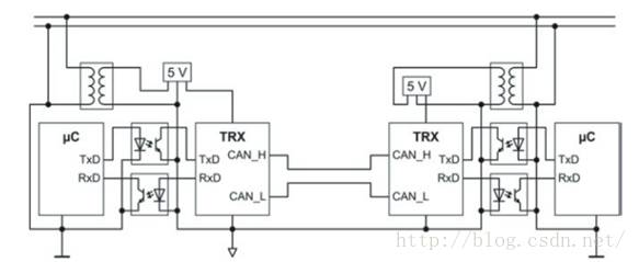
Figure 21-1: Schematic diagram of long-distance communication galvanic isolation circuit
22. CAN interface circuit and RS485 interface circuit
CAN bus and RS485 bus both use differential signals to transmit data. They are similar in terms of bus topology, terminal matching, signal attenuation, isolation and grounding, and the relationship between baud rate and communication distance. But CAN has some characteristics of its own, in the interface design, can not copy the RS485 interface circuit.
CAN bus is sensitive to signal delay, so high-speed optocouplers or magnetic coupling devices must be used for signal isolation to reduce signal delay. The TLP521 optocoupler widely used by the company cannot be used in the CAN interface circuit because of the excessive delay time (microsecond level).
The CAN bus is sensitive to capacitance. When designing the CAN interface circuit, you need to use CAN dedicated common mode inductors and professional ESD devices; you need to decide whether to add filter capacitors and filter capacitors to the CAN bus according to the maximum baud rate and communication distance of the application the size of.
 中文
中文 English


